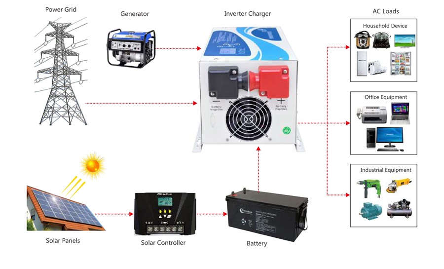
Working Principle of Pure Sine Wave Inverter DC voltage is divided into two circuits, one to supply power to the front IC to produce a KHZ level control signal and one to the front power transistor. The control signal drives the power transistor to switch continuously, which makes the high-frequency transformer produce low-voltage high-frequency alternating current at the primary stage. (At this time, the alternating current is low, but the frequency is quite high. The purpose is to make the transformer produce a high voltage at the later stage. The frequency of the former stage is proportional to the output voltage of the latter stage.) The high-frequency transformer passes through the high-frequency transformer. The output high frequency alternating current passes through fast recovery diode full bridge rectifier and outputs a high frequency several hundred V direct current to the rear stage power transistor. Then the control signal about 50HZ is generated by the rear stage IC to control the latter stage power transistor to work and output 220V 50HZ alternating current.
Of course, a complete inverter also needs some protection circuits, such as overload protection temperature protection, high and low input voltage protection and filter circuit. The filter in high frequency circuit is also very important. It is easy to produce some interference and parasitic coupling at high frequency, so filter circuit is needed to eliminate the influence of these factors to increase the stability of the circuit.
